Back to the Table of Contents
Safety Devices full roof rack instructions for
1994-1997 NAS Defender 90 Soft Top
The information on this page is to assist customers of ECR who have purchased a Safety Devices full roof rack with their installation.
Please do not link or post this page, or its contained information, to other internet sources.
First of all, thank you for your purchase!
This page will take you through the steps needed to install the Safety Devices (SD) rack system on a Defender 90 Soft Top. If you need instructions for a Station Wagon please go here.
The installation of the Safety Devices full roof rack can be a little tricky. Some items may need to be slightly modified and/or pushed/pulled into shape.
If you are uncomfortable with this type of custom vehicle work, or have very limited tools, you may want to think about having a professional install your rack system.
Tools you will need:
This is a minimum list. If you have more tools with sockets, extensions and such the job will be that much smoother.
Drill with 1/8", 3/16" and 3/8" drill bits, and phillips screw bit
Hammer and punch or automatic center punch
5mm allen wrench
8mmx1.25 tap and tap driver
10mm wrench
13mm wrench
3/4" wrench
7/8" wrench
2x 17mm wrenches
Tape measure
Masking tape and a marker like a Sharpie
Phillips screwdriver
Rat tail file or die grinder (possibly)
2 people (3 is better when putting the basket on top) will be required to lift and support the roof basket and rear ladder
A line up bar is a good idea as well
Anti-Seize compound for the threads on all the bolts is a wise idea
The first thing to do BEFORE you install the roof rack is to make sure your spare tire carrier and tailgate (tailboard) work correctly, move easily and latch correctly and do not have any damage. If your spare tire carrier needs work or your tailgate does not close correctly you must cure these issues BEFORE you install the roof rack system. If you do not fix things like worn tailgate hinges or bad tire carrier bushings before you start, it will cause you headaches on the install of the rack.
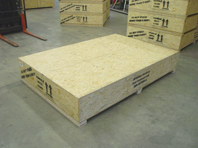
Then start by opening up your crate. Make sure the "this side up" arrows are pointing up and then remove the perimeter screws of the lid with a cordless drill type tool and remove the lid.
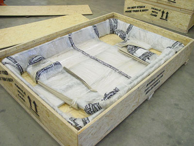
With the lid removed you will see the rack system.
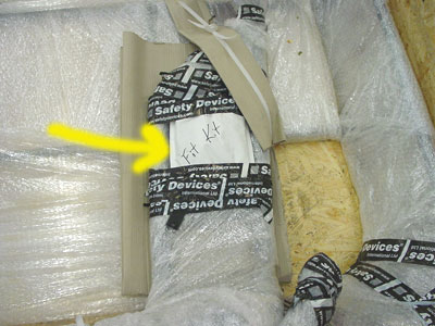
Taped to the rack you will find a bags that contains the needed hardware. It is a good idea to remove the bags and sort your hardware. Then you can start the very annoying job of removing all the protective materials.
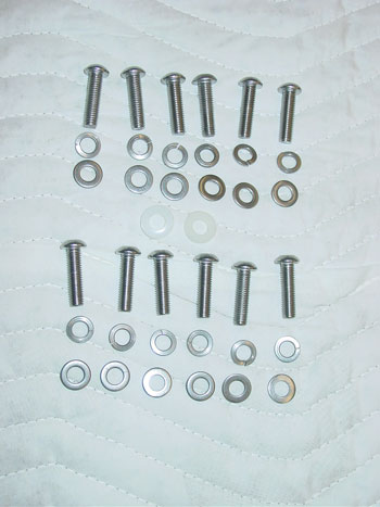
In the hardware bag from Safety Devices you will find 12 bolts that hold the ladder to the Rover. These bolts are too short and should be discarded. We have provided 12 correct length bolts and when combined with the lock washers and flat washers in the original fitting kit you will end up with the bolts as seen above. These are the 12 set ups that are used to attach the rear ladder to the Rover.
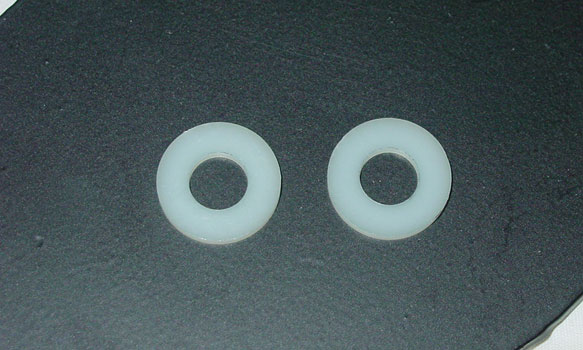
These 2 plastic washers are used to isolate the stainless steel bolts from the body on the LH lower mount.

These 8 set ups are the hardware that is used to attach the cross-bars to the safari cage feet.
Please note that some kits have bolts (as seen above) and some have allen headed bolts.
Both work equally well, it just depends on when your kit was shipped from ECR.
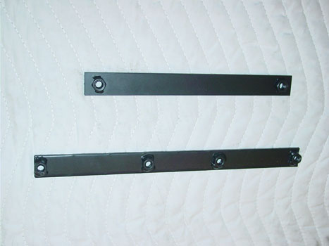
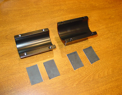
These are the LH backing plates. The top one goes behind the LH audio speaker and the bottom one goes in the wheel well just above the LH rear lights.

This is the RH backing plate. It goes behind the RH audio speaker.
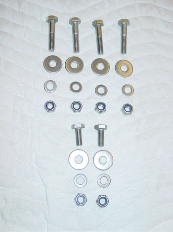
These are the bolts, washers and nuts that attach the roof basket to the crossbars and the rear ladder
Notice that 2 are shorter. The shorter bolts attach the basket to the rear ladder. The longer ones utilize the spacers (shown below) for the front basket to cross-bar mounts.
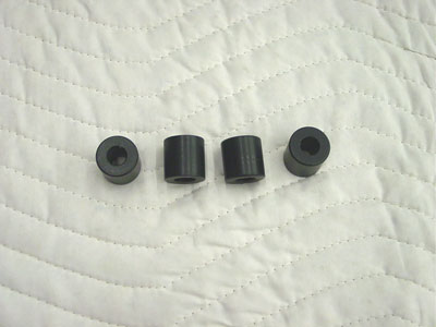
These are the soft top spacers.
Below you will see the old original style feet. These are no longer made or sold, but in case you are fitting an older kit we will leave the information.
If you have the new ECR ROX feet please skip down to the picture of them.
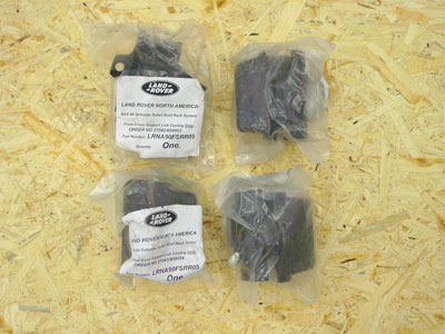
Along with the hardware you will find 4 rack feet in bags from Land Rover.
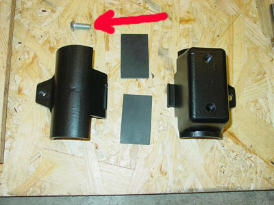
When you open the bags with the feet in them, you will find a bolt that holds the clamp together (red arrow). Discard this screw as it is not stainless steel.
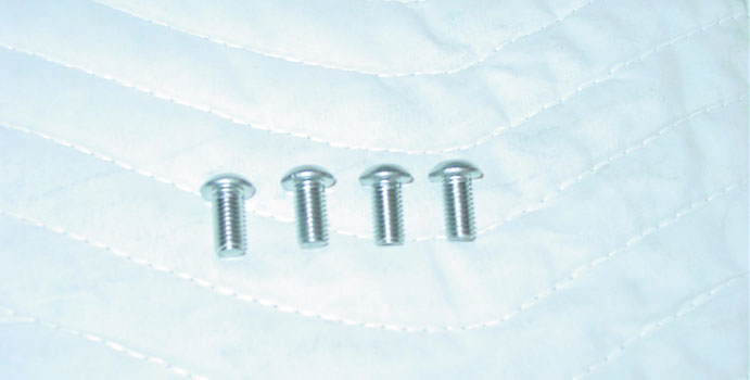
We have provided 4 stainless steel (SS) replacements in our hardware kit.
Before you start the install take your 8mmx1.25 tap and some lubricant and tap out the 3 holes in each rack foot. BE VERY CAREFUL doing this so that you do not break a tap or damage the rack foot. We DO NOT HAVE ANY MORE RACK FEET. So if you damage one you will be out of luck.
Do not try to install any hardware into the rack feet until you have tapped out all the threads.
ECR ROX rack feet:
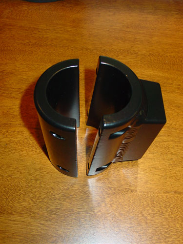
The new heavy duty ROX rack feet hold the roof rack in the same way, but they attach to the safari cage differently. They are a split 2 piece design, not a clam-shell design like the out of production units.
Install onto the truck is self explanatory Make sure to leave them loose so that you can adjust things as you go. When everything is set tighten them down a little at a time on each bolt to make sure they are square and you don't have a big gap on one side and none on the others.
The ROX rack feet use 4 pieces of rubber for each foot, to help protect your truck's safari cage.
2 pieces are installed in each half. 4 pieces of self adhering rubber have been provided with your rack system.
ASSEMBLY:
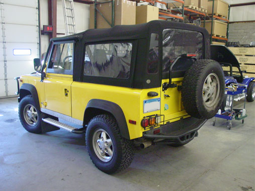
Park the Rover on safe level ground.

Remove the spare tire.
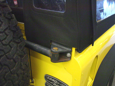
Remove the soft top a little in order to expose...
the 4 bolts that hold the upper RH mount of the spare tire carrier to the body of the Rover.
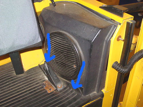
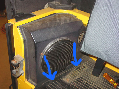
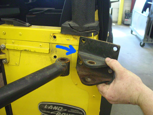
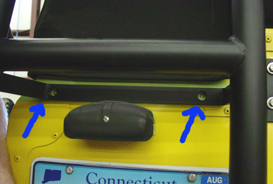
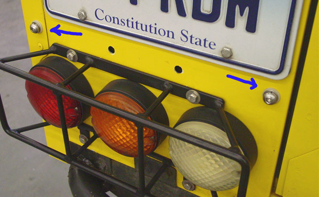
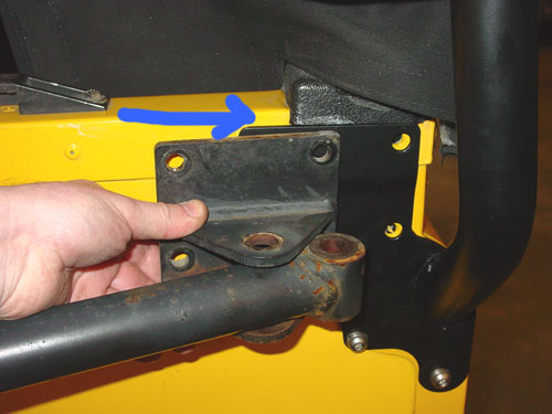
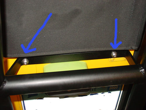
The Soft Top Defender 90 we did this installation on had 4 jump seats. Most do not as it was never offered from the factory, so ignore the seat brackets and jump seats in these images. Now remove the speaker housing by lifting up the rubber cargo cover and removing the 2 screws that hold the bottom of the speaker housing to the body (see blue arrows). Once the 2 lower screws have been removed pull the bottom of the speaker pod out and rotate the pod out, unplug the speaker and set the pods aside.
Note: It is common that the screws to remove the speaker pods will be stripped and/or be rusted in place. You may have to drill or grind them off and replace them with new.
Remove the LH speaker housing as well.
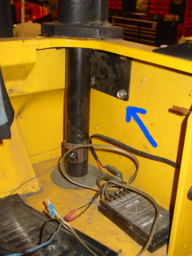
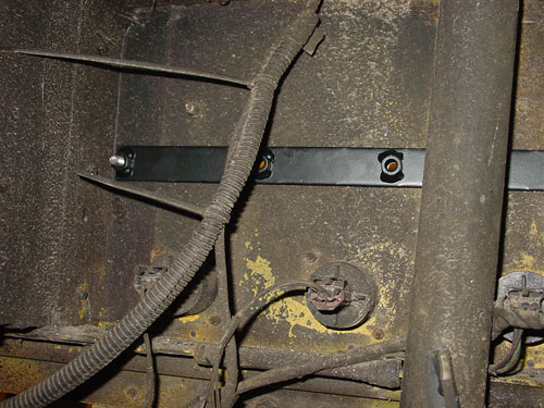
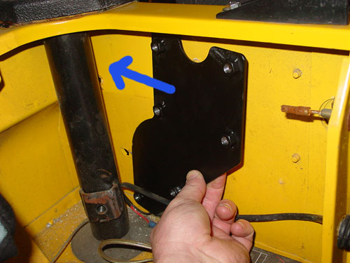
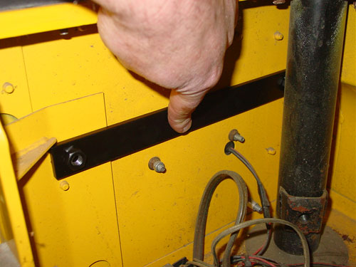
Once the speaker housing is removed you will be able to see the original backing plate (blue arrow).
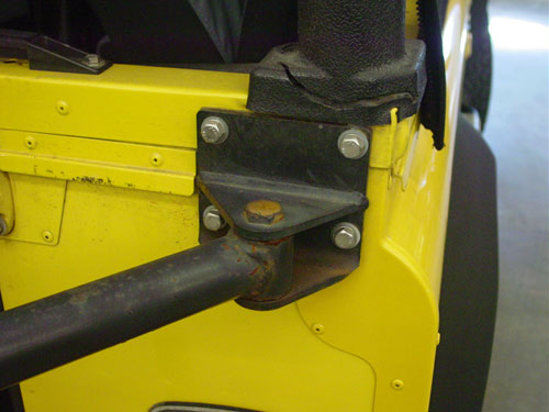
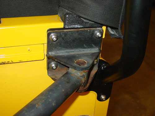
Now remove the four bolts that secure the upper RH tire carrier pivot bracket to the truck..

and remove the original backing plate.

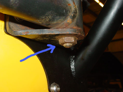
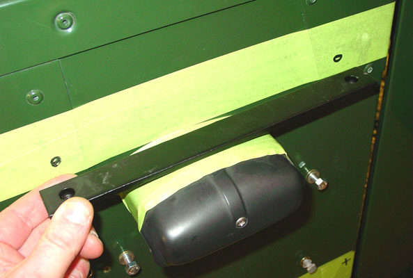
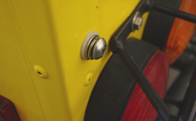
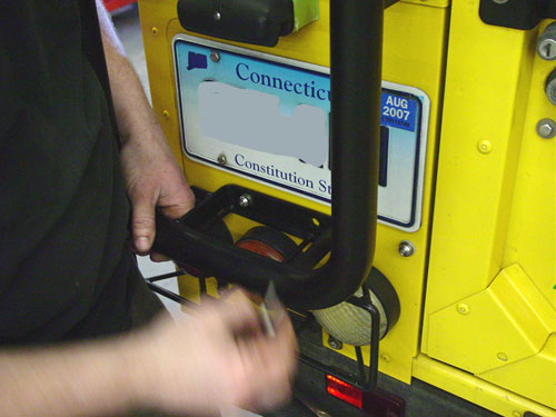
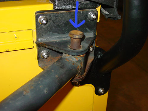
Remove the locking nut on the bottom of the upper RH spare tire carrier pivot bolt, located at "A" (detail image of "A" below), and then remove the pivot bolt itself, located at "B".
Once the pivot bolt is removed slid the pivot bracket out of the way.

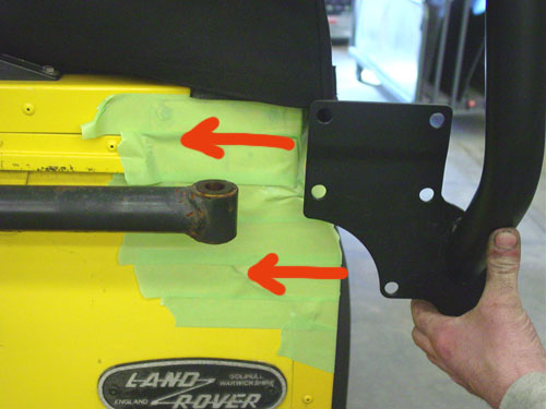
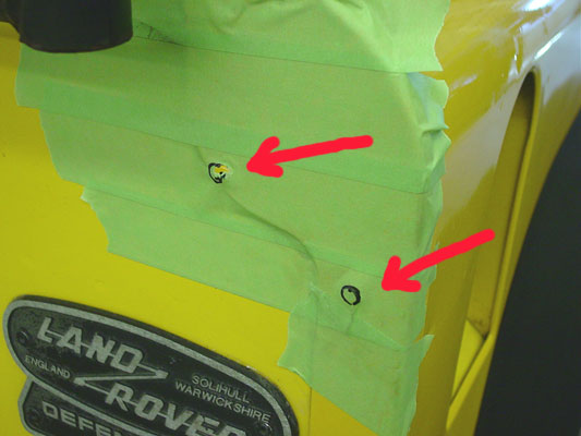
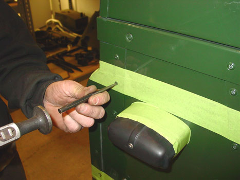
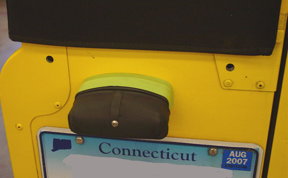
We suggest that you use some tape to protect the paint on your truck. Tape up the areas shown above.
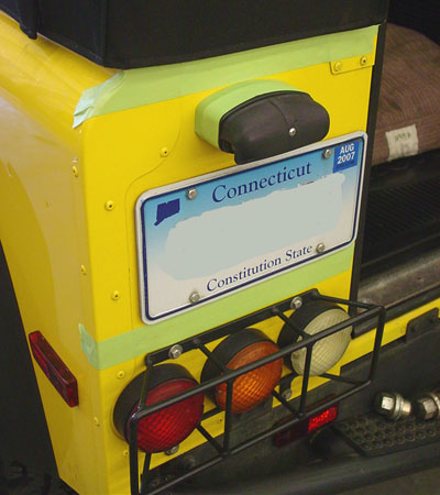
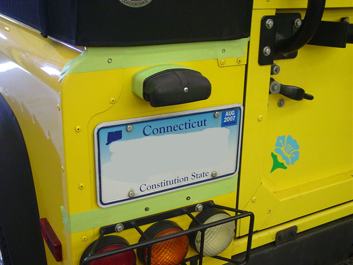
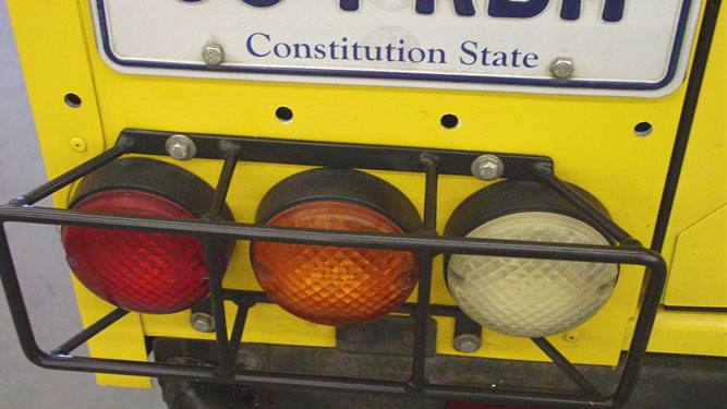
Also tape up the plate light spacer, as the rear ladder will rest on this and the tape will keep it from damaging the part.
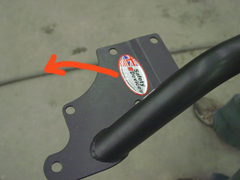
Next remove the decal off the rear ladder. It peels off easily.

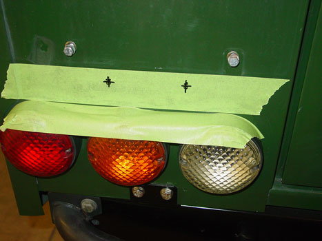
Now punch through the tape on the 4 top holes so that you can see through them. These 4 holes dictate where the rear ladder will mount on the RH side.
Next, using 2 people, offer the rear ladder up to the truck and snake the RH side behind the spare tire carrier and line up the top 4 holes on the rear ladder with the 4 holes on the Rover. You can use some bolts to locate the rear ladder on the RH side so that it stays in the right spot.
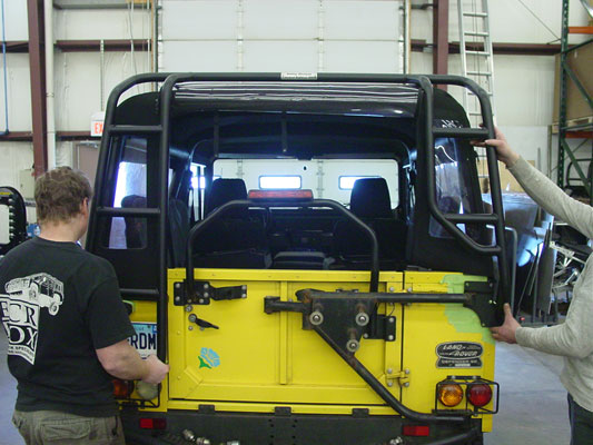
Hold the rear ladder so that it matches the lines of the truck and looks good. The mounting plate should not be too low or too high, it should nicely flow with the lines of the Rover. The lower two mounting holes on this side should line up with the 2 rivets on the body. You will see when it is right and when it is wrong.
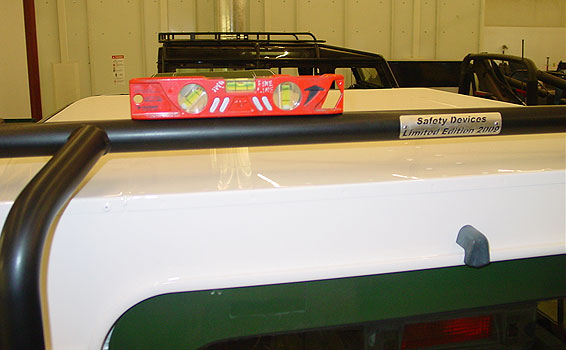
Use a level or your eye to make sure that the ladder looks good on the truck and that it is not tilted to one side or the other. You can also measure from the ladder down to the top to check that things are correct.
Once you are happy with the look of the rear ladder placement, mark the holes on the LH side.

We find that in most cases this part of the rear ladder is about 1/8" above the plate light if everything is in the right spot, but each Defender is different.

Mark the lower holes on the LH side as well and...
mark the 2 lower holes on the RH side. These should line up closely with the 2 rivets on the body.
Now take the rear ladder away from the truck.
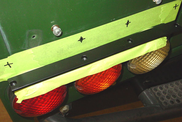
The LH side should look like this.
The lower LH mount holes will be shown on the tape as seen above, but this area has 4 holes in total for the ladder and its backing plate.

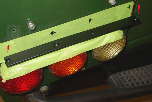
Locate the long backing plate and hold it up to the truck so that the 2 inner holes match up with your marks on the truck and mark the 2 outside holes.
You will end up with marks like this. Be sure that the lower backing plate is in the right way. One way is right and one way is wrong. The right way is shown above.
This is the wrong way, you can see that bolt hole farthest to the right would be off the body and into the door.
It is a good idea to check that the backing plates that go inside the car will line up with the holes you have marked.
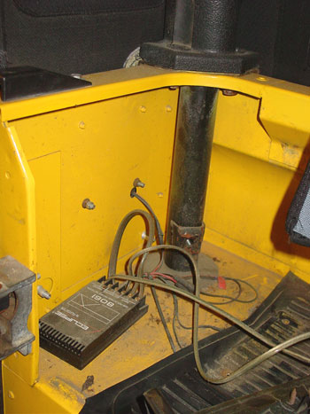
Before you drill make sure there are no wires or other items behind where you plan to drill.
Next use a center punch and a hammer, or an auto-punch, and mark the holes to be drilled. Doing this prevents the drill-bit from walking and keeps the hole where you want it.

Once all the holes are center punched start by drilling a 1/8" pilot hole. Do not start with a large drill bit. Drill all the holes out with the 1/8" bit. Be sure there are no wires behind where you are about to drill.

Then follow up with the 3/8" drill bit on all the holes and remove the tape.
The RH side should look like this. You will have to drilled out two rivets on the body corner. If these holes goes off center, simply file it into shape. They rarely line up perfectly and some filing or grinding will be required.
The LH side should look like this.
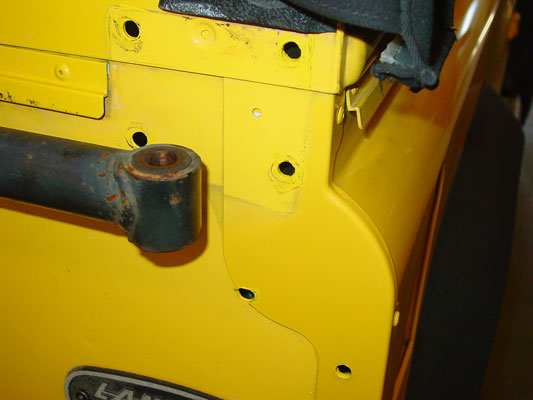
The corner cappings are made of steel, so before you install the ladder it is wise to use some primer and paint to touch up the raw steel edges so that rust does not occur on the steel parts. You can see we have done this in the image above with some AA Yellow paint. Do this on both sides of the truck.
Now you can hold the LH lower backing plate inside the 90 and make sure all the holes line up and start the bolts. If they do not, do some filing or grinding until they do. Make sure not to pinch any wires under the backing plate (plate light wiring).
Then install the 2 outer bolts with the plastic washers. These outer 2 bolts on the LH lower mount do not go through the ladder itself. They just help spread the load over the backing plate so that the ladder is secure. The bolts supplied are stainless steel and SS corrodes the body of a Rover very quickly, so use the white isolation washers between the flat washer and the body.
This will help prevent corrosion. You really only need to do this on the inboard lower bolt, but we have supplied 2 washers so that everything looks uniform.
Now it is time to install the rear ladder. On the RH side offer up the backing plate on the inside of the tub.
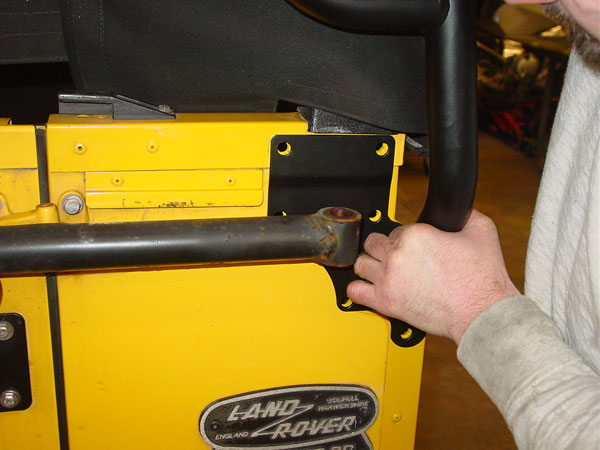
Then have the ladder held in the correct location outside the truck and start the 2 lowest bolts (the 2 bolts would be below the hand in the picture above) from the outside, through the ladder, through the body and into the backing plate. You should use a flat washer and a locking washer on these bolts. Use the 5mm allen wrench to start the bolts. Do not tighten them all the way, only get them started and snug.
Install the 2 lower bolts on the LH side into through the ladder into the backing plate. Keep everything loose at this point.
Now snake the upper RH pivot bracket back into place.
Install the 4 bolts through it into the backing plate, again, keeping everything loose and grind or file as required.
Now install the upper LH backing plate behind where the LH audio speaker was.
It is almost a given that you will need to file, re-drill or open up some holes, or even grind or file a bit off here and there. No two Defenders are truly the same, so expect a little custom work to get all the bolts to line up with the backing plate. Do not force anything. Keep filing and adjusting until everything goes smoothly. Forcing things with SS bolts means they will most likely gall, and this will create a world of hurt for you trying to drill out bolts and get new hardware.
Now reinstall the upper pivot bolt...
and its locking nut.
Now move the ladder around slightly to make sure it is level and that the tire carrier works correctly. When it does tighten up all the securing bolts. You may have to make adjustments here and there.
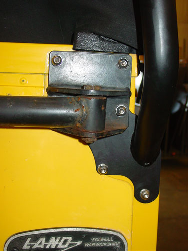
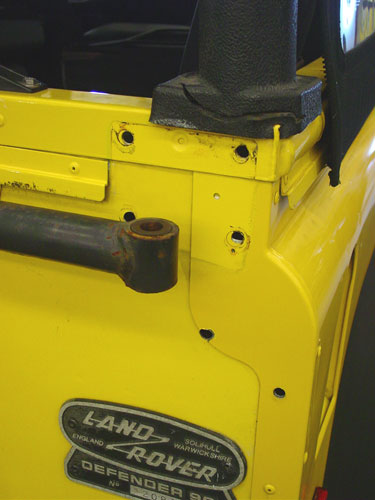
When you are done the RH side should look like this and the tailgate should close easily.
Then clean up the interior of drilling debris and re-install the interior parts that were removed.
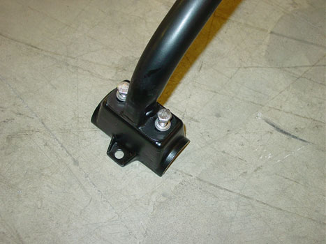
Locate the 2 front cross bars and attach the rack feet to them as shown. The bolts require locking and flat washers as shown. The feet should go on as shown, with the bolt tab to the outboard side. Attach all four feet to the cross bars, but leave the bolts loose. DO NOT damage any feet. There are no replacements at this time.
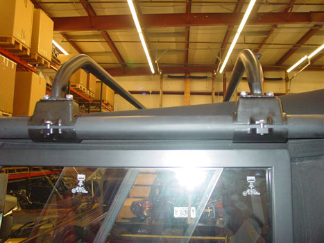
Set the 2 cross bars over the roof and onto the safari cage bars above the doors.
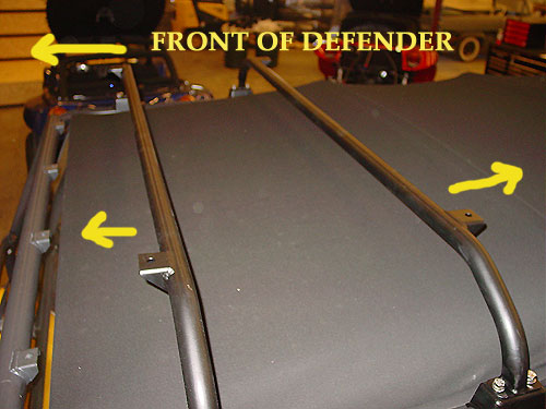
Be sure that the mounting tabs on the cross bars are facing the ways as shown by the yellow arrows. The front one faces forward and the rear one faces rearward.
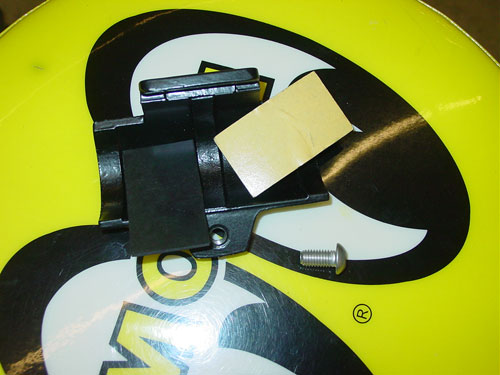
Locate the remaining parts for the rack feet. You will find 2 self adhesive rubber pads and a bolt. If you didn't read it before, discard the bolt that came in the bag with the feet. We have supplied a SS one for you instead. Be sure to use some anti-seize on all these bolts if you ever want to be able to get the rack off again. If any bolt feels tight going into the rack feet STOP! Go back and re-tap the hole and check the bolt. Anything forced will likely wreck the feet or ruin the bolt.
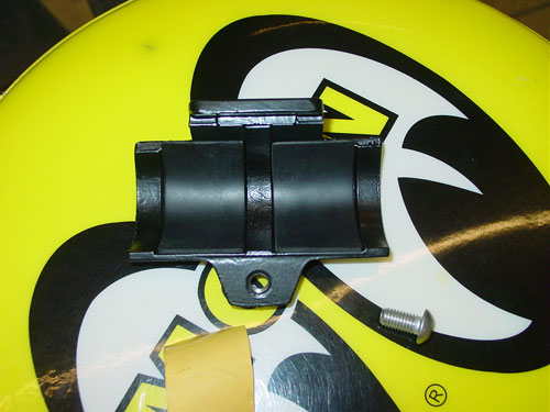
Peel the rubber strips and stick them into the lower sections of the feet as shown above.
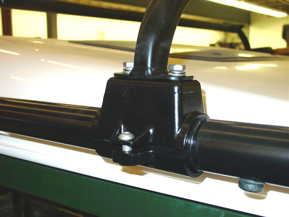
Now attach the lower portion of the clamp and start the bolt. Do not tighten the bolt at this stage, just start the threads.
The Rover should look like this at this point. Rear ladder on and secure and the 2 front cross bars in place, but all hardware for them loose so that they can slide into their final location.
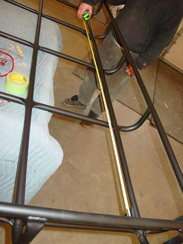
Take a measurement on the roof basket between the mounting points.

The mounting points are the corner brackets shown above.
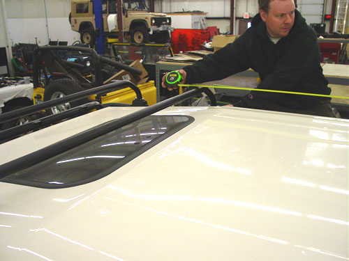
Take those dimensions and roughly set up the front cross bars so that the rack will fit once you install it on the truck. The front cross bars should still be loose so they are easy to slide to the right locations. Once everything is pretty close lug the basket to the top of the truck and set it down as close to where it goes as possible.
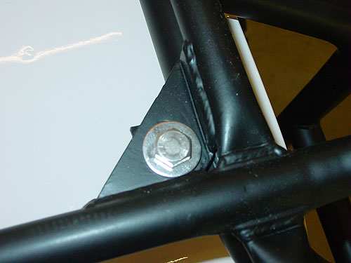
Using the SS hardware and the large flat washer, as seen above install all 6 bolt assemblies to attach the roof basket to the supports.

Use the provided spacers for the 4 front mounts. There is some space in the holes so the rack can be moved slightly to make sure it is square and straight. Once it in the right place tighten the back two mounting bolts.
With the 2 rearmost mounting bolts securely attached to the rear ladder you can pull or push the rack around a little to make sure everything is right.
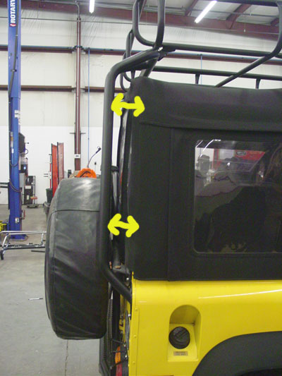
In most cases you will need to tug the basket forward a little in order to achieve an even gap between the back of the 90 and the ladder. Adjust as needed and then tighten everything, and all the hardware down, on the entire rack.

Congratulations!

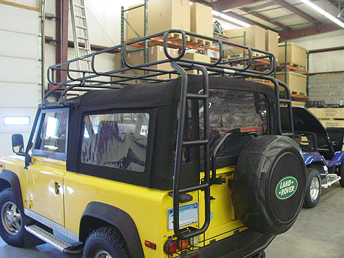
You now have a great looking and functional rack on your Defender 90 Soft Top!
Go for a ride and show it off to your friends, or better yet pack it with camping gear and go on a trek!
Thanks again for your purchase!
ECR is your Defender source and we work hard to not only bring you the best service and restorations on these unique vehicles, but also hard to find parts like the Safety Devices rack system.
East Coast Rover Co.
Contact Information